[{"url":"/products","name":"Products","linkClass":null,"categoryCode":null},{"url":"/interface-electronic","name":"Interface Electronic","linkClass":null,"categoryCode":null},{"url":"/interface-electronic/global-interface-electronic-discover-overvoltage-protection-specialty-electronics","name":"Overvoltage Protection","linkClass":null,"categoryCode":null},{"url":"/interface-electronic/global-interface-electronic-discover-overvoltage-protection-specialty-electronics/electronic-circuit-breakers","name":"Electronic Circuit Breakers (ECBs)","linkClass":null,"categoryCode":null},{"url":"/interface-electronic/global-interface-electronic-discover-overvoltage-protection-specialty-electronics/electronic-circuit-breakers/why-electronic-fuses","name":"Why Electronic Fuses?","linkClass":"active","categoryCode":null}]

Electronic Circuit Breakers
WAGO’s ECBs offer greater safety for protecting your system. Thanks to their communication capabilities, they also provide data about the current status of the channel and the connected loads.
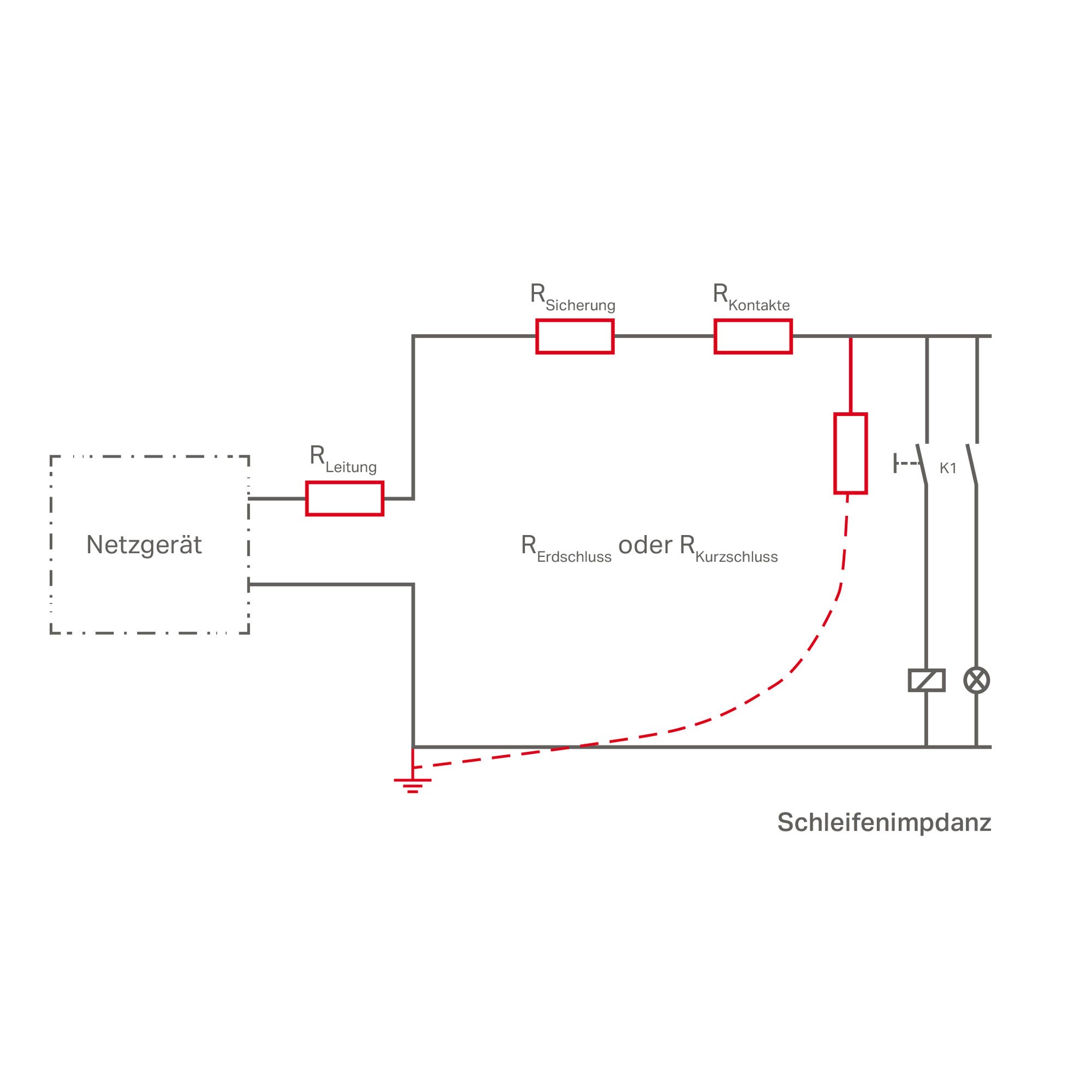
Why Secondary-Side Fuse Protection?
On the secondary side, switched-mode power supplies provide DC voltage to control circuit loads (e.g., controllers, operating panels, displays and auxiliary relays). These control circuits also call for wiring protection and if the load has no protective unit of its own, device protection as well. Furthermore, Machinery Directive EN 60204 requires the detection of hazardous ground faults in control circuits and switching off within five seconds.
The overcurrent protection in primary switched-mode power supplies reacts very quickly to overcurrents on the output side. Selective protection of individual current paths in the secondary circuit via fuses or conventional circuit breakers is often ineffective if the power supply cannot deliver a brief overcurrent.
What Types of Fuse Protection Are There?
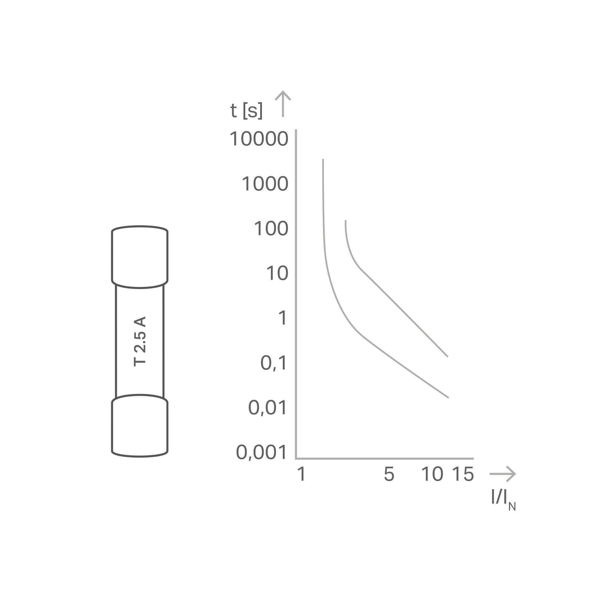
Thermal
Possible applications:
- Low-voltage, high-power and DP fuses
- High overcurrents required for fast tripping
Explanation:
- In the example: ten-fold overcurrent (related to fuse nominal current): tripping within the range 30 ms (best case) or 200 ms (worst case)
- Only two-fold overcurrent: tripping within the range 2 s (best case) or >100 s (worst case)
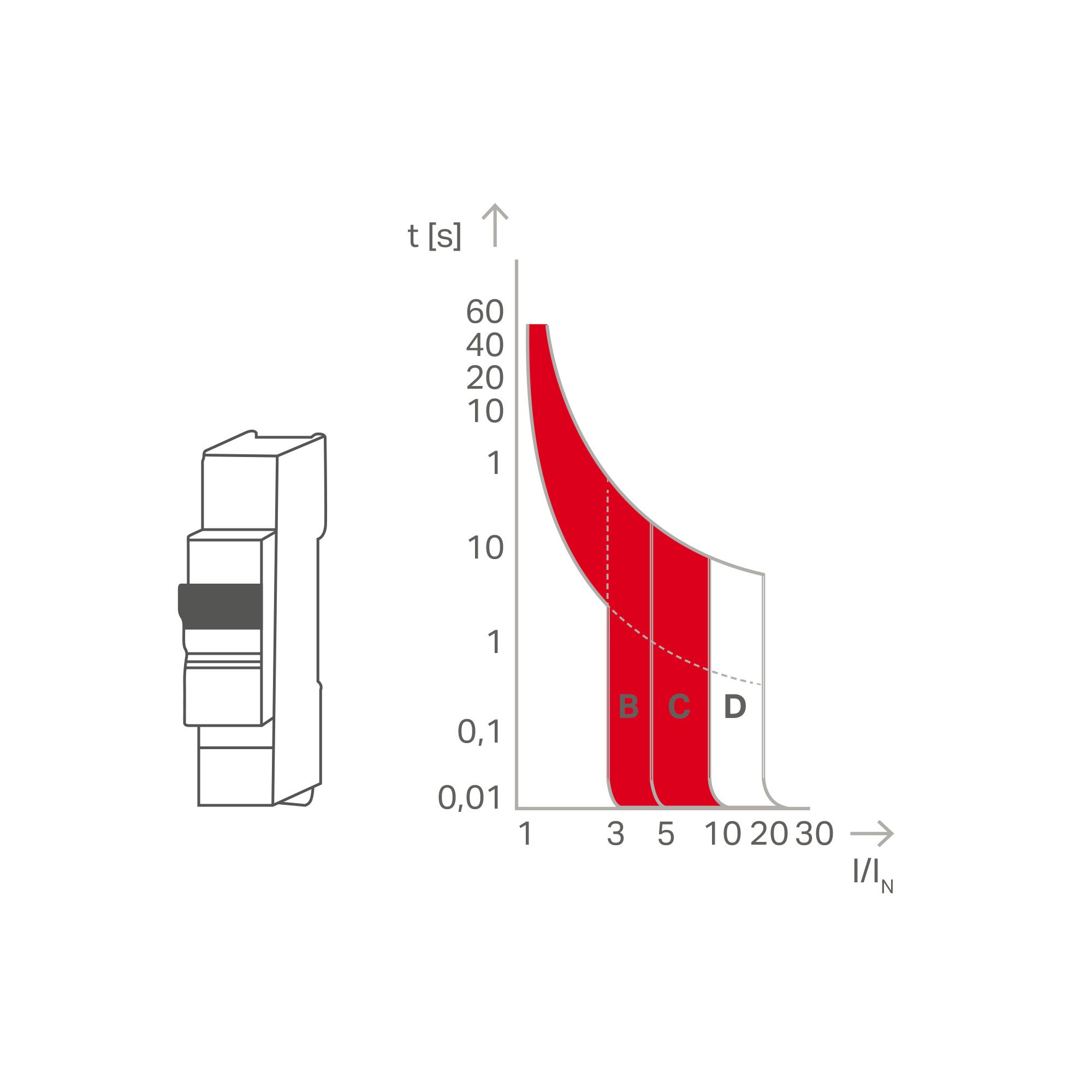
Thermal and Magnetic
Possible applications:
- Found in circuit breakers or motor protection switches
- High overcurrents required for fast tripping
Explanation:
- In the example: three- to five-fold overcurrent for B-characteristic and AC operation, additional safety factor 1.2 or 1.5
- Thus, in the worst case scenario, a tripping current of 7.5 times the nominal current is necessary.
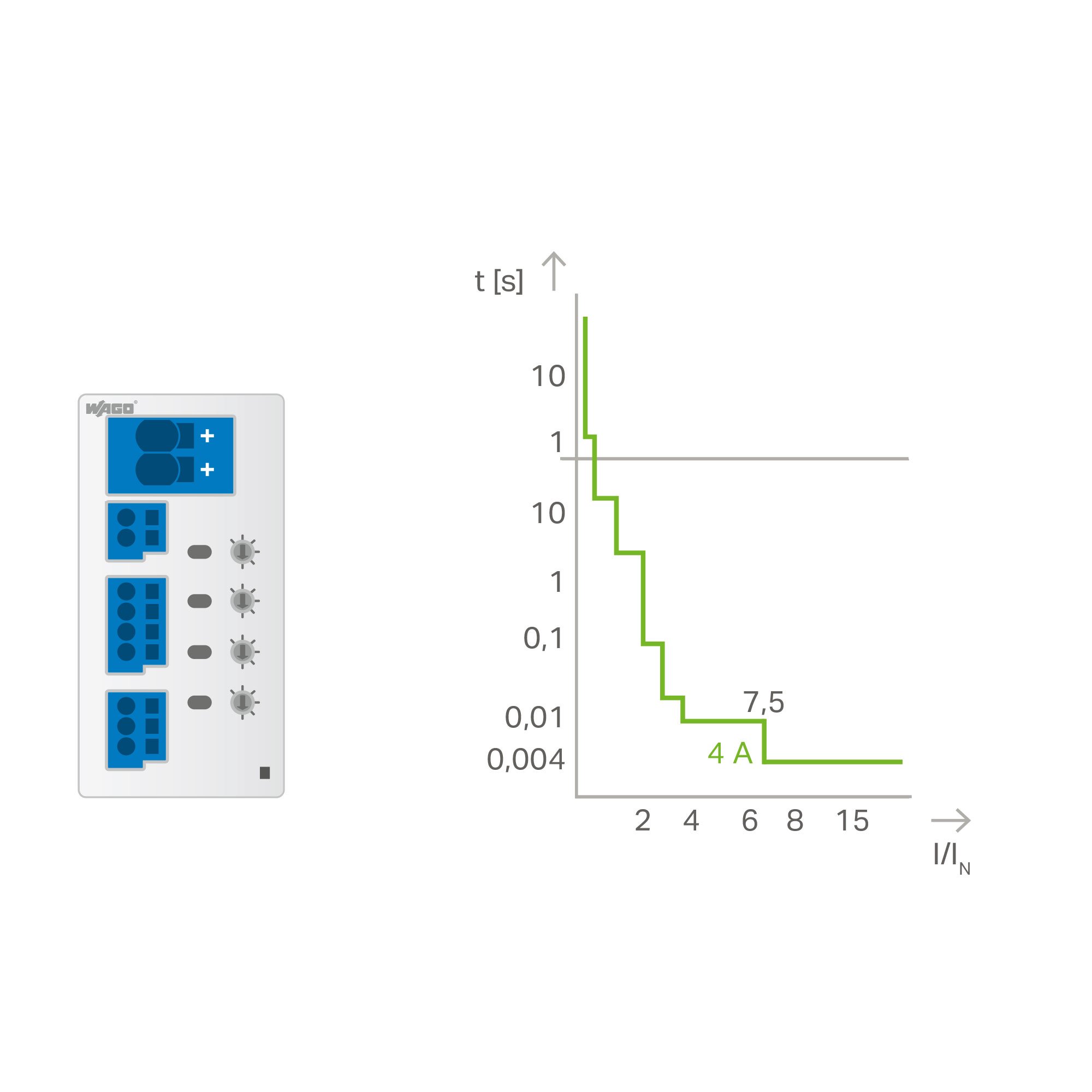
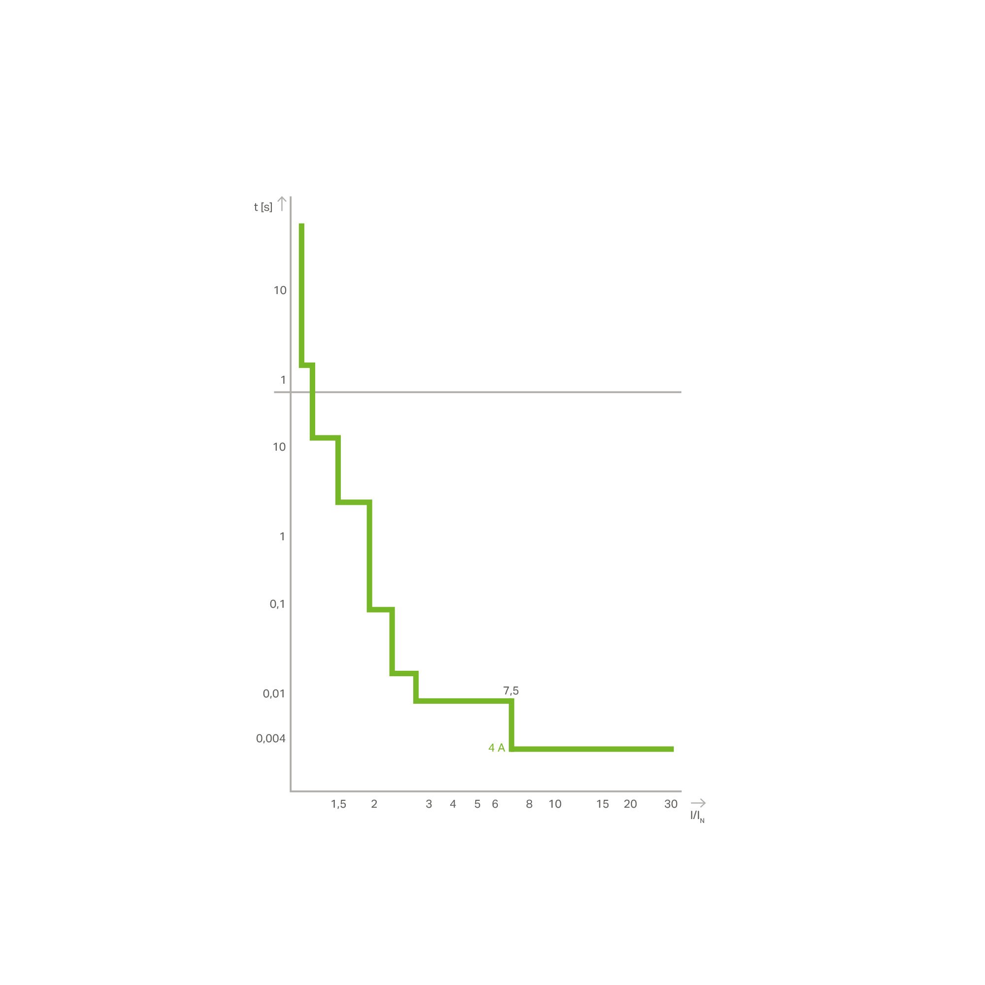
Electronic
Possible applications:
- Ensure precision settings
- Reaction within a short time – even at low overcurrents
- Protection of long cable runs and small cross sections possible
Explanation:
ECBs ensure reliable protection, even at low overcurrents and with long cable lengths.
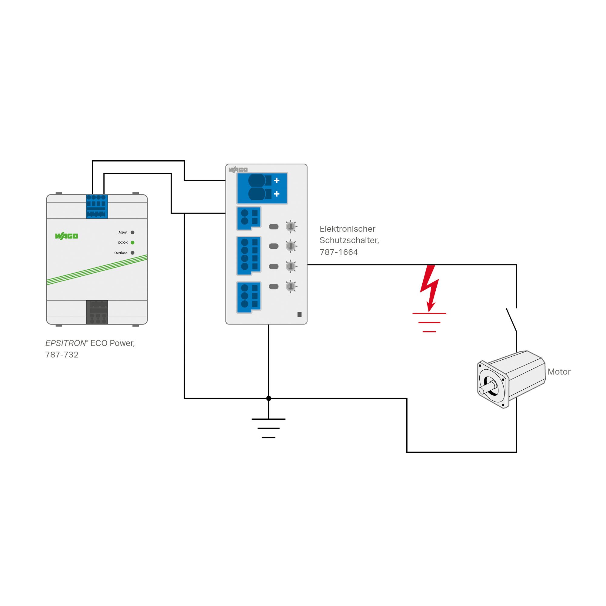
How Does an ECB Function?
The ECB verifies that the output current is greater than the nominal current. As soon as the output current exceeds the nominal current, the output is electronically switched off by a semiconductor switch. The trip time depends on the magnitude of the overcurrent. The measurement of the output current, processing and calculation of the tripping time, as well as actuation of the semiconductor switch are performed by a microprocessor that monitors one or more output channels. The corresponding tripping times can be taken from the graph on the right.
- Switch off secondary-side overcurrents and short circuits – even with long cable runs and small conductor cross-sections – precisely, quickly and repeatedly
- Selectivity, especially with ECBs having active current limitation
- Remote operation via digital input and output
- Readout functions (communication) through serial data transfer via digital input and output
- Advantageous installation size and width, for example, eight output channels in just 42 mm (1.653 inch) that saves more than 70% of installation space compared to miniature circuit breakers
- Nominal current assignable for each channel
- Satisfy EN 60204-1 requirements for dependably switching off ground faults after five seconds
Digital Signaling (DI/DO)
- The digital input (DI) serves as a remote input for collectively resetting all tripped channels.
- The digital output (DO) provides a collective signal indicating whether any channel has tripped due to overcurrent.
- Simple collective signaling is enabled via push-in type jumper bars.
Manchester Protocol
- The digital input (DI) serves as a remote input for switching specific channels on and off using pulse sequences.
- The digital output (DO) transmits the status, current load, and selector switch position.
- The digital output (DO) also provides collective signaling.
- Optionally, input voltage and output or rated current per channel can be transmitted.
IO-Link
- IO-Link interface
- Read out the status, configured rated current, and actual voltage/current values for each channel
- Configure the rated current, switch channels on/off, and reset individual channels
Modbus RTU
- Modbus RTU interface
- Easy integration into existing systems and reliable cyclic data transmission
- Read out the status, configured rated current, and actual voltage/current values for each channel
- Configure the rated current, switch channels on/off, and reset individual channels
Additional service offerings: