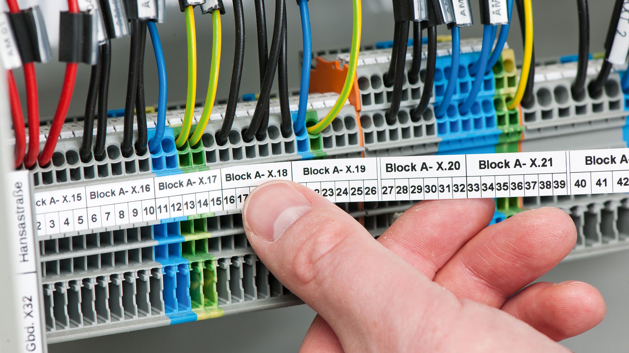
[{"term":"Libraries_BA","id":0,"type":"QUICKLINKS"},{"term":"Instructions","id":1,"type":"QUICKLINKS"},{"term":"WAGO-I/O-PRO","id":2,"type":"QUICKLINKS"},{"term":"Building","id":3,"type":"QUICKLINKS"},{"term":"221","id":4,"type":"QUICKLINKS"}]
Practical tips 31 August 2020

Safety and Standards: Practical Tips for Our New Products

We have summarized all of the important information for the safe, standard-compliant usage of WAGO products.

Practical Tips

  • Go to Approval Marks and Standards
  • Go to Temperature Measurements
  • Go to Installation and Application

Practical Tips on Approval Marks and Standards

  • Safe, Standard-Compliant Products, Always on Hand
  • Standards and Approval Marks for Installation Connectors
  • International Approval Marks and Information about WAGO Installation Connectors

Tip: Safe, Standard-Compliant Products, Always on Hand

According to the applicable laws, a product may only be brought to the market in the EU if it complies with the basic requirements of any applicable EU directives that may exist for this product. The CE marking is used by a manufacturer, distributing company or EU-authorized representative to declare per EC Regulation 765/2008 “that the product is in conformity with the applicable requirements set out in Community harmonisation legislation providing for its affixing.”
praxistipp-entscheidung.jpg

Splicing connectors fall within the application scope of the Low Voltage Directive 2014/35/EU.

In the Low Voltage Directive’s reference list, the standard applicable to splicing connectors is the EN 60998 series. All WAGO splicing connectors have been tested on the basis of the standards in this series by independent testing institutes and certified accordingly. Based on these test results and certifications, WAGO declares that these products comply with the requirements of the Low Voltage Directive for these products and affixes the CE marking accordingly.
Furthermore, WAGO labels its splicing connectors with the ENEC mark. Use of this mark is only permitted if further requirements (like application of a quality system meeting at least the level of ISO 9000, regular inspection of the end products and verified production controls) have been fulfilled during production and proven to an external testing institute. Compared to similar certifications of national testing institutes (e.g., the VDE mark), for WAGO customers, the ENEC mark confirms compliance above and beyond the applicable standards of the corresponding country. In fact, the ENEC mark covers all certifications of all national testing institutes that have joined the ENEC agreement, regardless of the testing location. Currently, 25 well-known testing institutes are authorized to issue the ENEC certificate. These include VDE Testing and Certification Institute GmbH, SGS Fimko Ltd., DEKRA Certification BV and the British Standards Institution.

Tip: Standards and Approval Marks for Installation Connectors

DIN VDE 0100-520 for electric cable and wiring systems in buildings clearly specifies that, in the construction of these systems, only connectors meeting the applicable European standards and the German product standards derived from them are permitted for connecting conductors. DIN EN 60998 (VDE 0613) is cited for splicing connectors and DIN EN 60947 (VDE 0611) for rail-mount terminal blocks. In the worst case, the party constructing such systems must verify that the products used satisfy these standards. Therefore, WAGO submits all its connectors to independent testing agencies in accordance with these standards to ensure maximum product safety for electrical system constructors. The approval marks that have been granted are affixed to the packaging and products. WAGO also provides the certificates upon request.

tabelle.jpg

Tested and Approved

There are three approval processes, leading to three different approval marks, for certifying connectors for use in Germany or all of Europe. These approvals differ in terms of the product standards they apply to and the countries in which they are valid (see table).
WAGO follows the ENEC procedure in gaining new approvals for splicing connectors complying with EN 60998. This procedure corresponds to the process for obtaining the VDE mark, except it is valid for all of Europe after a single test. Because the ENEC procedure makes no provision for approvals according to EN 60947, but an approval for these products must be applicable everywhere in Europe, new approvals for rail-mount terminal blocks are sought through the CCA procedure. The CCA procedure is based on a national approval within a European country and is also certified with the corresponding national approval mark. An additional CCA certificate extends the validity of the national approval to Europe.
Stay on the Safe Side with WAGO
The installer is responsible for selecting approved products and installing them correctly. With the approval in accordance with the applicable product standards of all connectors its wide range of products, WAGO provides the perfect basis for standard-compliant installation. Moreover, all WAGO connectors undergo internal tests with even more stringent demands on quality. Only after these tests have been passed are the products released, giving the user the high level of safety and reliability WAGO is known for.

Tip: International Approval Marks and Information on WAGO Installation Connectors

WAGO’s installation connectors are used by electrical system installers around the world. Approval according to the applicable standards is a requirement for international use. For this reason, WAGO’s installation connectors and their packaging carry national and international approval marks, as well as further information specific to the application domain. This lets users know that, with WAGO’s installation connectors, the material they work with is standard-compliant.

In Europe, WAGO certifies its installation connectors according to the ENEC process to ensure that the European standard EN 60998 is met and that the connectors conform to all procedures for obtaining the VDE mark.

pruefzeichen.jpg

With this single test, WAGO products are granted approval covering all of Europe. This approval is indicated by the ENEC approval mark. An identification number representing the certification agency is listed after the approval mark. Technical specifications regarding nominal current and voltage, as well as the conductor type and cross-section that can be used, are also affixed. Information about the conductor types is given in English. WAGO installation connectors labeled with an “r” (rigid) can connect solid or stranded conductors. WAGO installation connectors labeled with an “s” (solid) connect solid conductors. WAGO installation connectors labeled with “str” (stranded) connect stranded conductors. WAGO installation connectors labeled with an “f” (flexible) connect fine-stranded conductors.

WAGO installation connectors that were certified before the ENEC test have national approval marks such as the VDE approval mark, the KEMA KEUR approval mark (Netherlands) or the DEMKO approval mark (Denmark). These approval marks are also followed by technical specifications. Usually only one conductor cross-section is indicated, not a cross-section range. WAGO installation connectors can connect at least the next two conductor cross-sections smaller than this stated cross-section in accordance with EN 60998.

In addition to the European approvals, WAGO’s installation connectors are also certified for the North American market, specifically from Underwriters Laboratories (UL) for the US and the Canadian Standards Association (CSA) for Canada. In the past, these two certification agencies jointly introduced the “cULus” mark. In accordance with this standard’s requirements, information about the application area is indicated after the mark.

Unlike Europe, North America uses the American Wire Gauge system (AWG) instead of the metric system (mm²) to specify the conductor cross-section.

WAGO’s installation connectors are also used by electrical installers in Japan. Therefore, the connectors also fulfill the requirements of the Product Safety Electrical Appliance and Material Safety Law (PSE standard). This certification is issued by Japan Electrical Testing Laboratories (JET). Here too, information about standards compliance and permissible conductor diameters is presented. In Japan, the conductor diameter is used instead of the cross-section. Because WAGO’s installation connectors are optimized for installation size, the approval marks and corresponding information cannot always be presented sequentially.

Practical Tips for Temperature Ranges

  • Permissible Temperature Ranges for WAGO Installation Connectors
  • Correct Evaluation of Installation Terminal Block Heating

Tip: Permissible Temperature Ranges for WAGO Installation Connectors

Local operating conditions vary as widely as the actual applications themselves do. Surrounding air temperature is a very important operating parameter, since it places special requirements on the heating characteristics of the installation material.

The European standard for splicing connectors, EN 60998, defines three different temperature specifications for use of installation connectors:
  • Maximum surrounding air temperature
  • Maximum heating
  • Maximum continuous service temperature
Based on these specifications, the electrician must decide whether or not the respective specific installation connector is suitable for the application at hand. Most of the time, the maximum surrounding air temperature is the only specification available for making this decision. For installation connectors approved per EN 60998, without any other specifications, a maximum continuous operating temperature of 85 °C (185 °F) is specified by the standard. Assuming that the maximum heating level is fully reached with the respective connector, a permissible maximum surrounding air temperature of 40 °C (104 °F) results from subtracting the maximum permissible heating of 45 K (equivalent to 45 °C/113 °F) specified in the standard.
Praxistipp_Tabelle.png

Manufacturers can also specify different temperatures.

These are usually also continuous operating temperatures. The maximum permissible surrounding air temperature is obtained by subtracting the maximum heating level of 45 K from the specified temperature.
This is the option WAGO applies. Unless otherwise indicated, a maximum continuous operating temperature of 105 °C (221 °F) applies to all WAGO installation connectors. When the maximum heating level of 45 K is subtracted from the limit, a permissible surrounding air temperature of 60 °C (140 °F) still applies. This means that WAGO installation connectors are normally approved for higher temperatures and exceed the requirements set forth in the standards.
Approvals for higher surrounding air temperatures are possible
DIN EN 60998 also offers the option of approving connectors for higher surrounding air temperatures. This can be accomplished if the manufacturer modifies the connector’s design by using additional or higher-quality materials to minimize heating of the connectors. Connectors that are approved in standards for continuous operating temperatures greater than 85 °C (185 °F) are provided with a T mark in their certificate based on EN 60998, e.g., T55. This T mark consists of the letter “T” in front of a number, indicating the maximum surrounding air temperature for the connector.
Maximum Surrounding Air Temperature
  • Maximum temperature of the surrounding air in which the connector can be used, in °C. The maximum surrounding air temperature also corresponds to the T mark specified by the standard (e.g., T85).
Maximum Heating:
  • Greatest permissible temperature increase in Kelvin with the least favorable electrical load.
  • This is produced by the current’s flow through the connector. Splicing connectors approved per EN 60998 are restricted to maximum heating of 45 K (corresponds to a temperature increase of 45 °C/113 °F). As a rule, connector manufacturers apply this maximum permissible heating value in the design of their connectors to ensure that the materials used for the conductive connector components remain affordable.
Maximum Continuous Operating Temperature:
  • The maximum temperature in °C that the connector is allowed to reach during continuous operation.
  • This temperature is the sum of the maximum permissible surrounding air temperature and the maximum permissible heating level.
Calculation of the permissible surrounding air temperature is not required for connectors with this marking. This temperature is indicated directly here as a number. Because its heating level is markedly lower than that permitted by the standard, the new 221 Series COMPACT Splicing Connector, for example, has a T marking of T85 for all conductor types. This indicates that the connector can be used at surrounding air temperatures of up to 85 °C (185 °F).
Some WAGO installation connectors have been developed for special applications. These connectors therefore frequently have specific maximum temperature ranges which usually far exceed the requirements of the standard. The table below lists the temperatures for WAGO’s installation connectors:

Tip: Correct Evaluation of Installation Terminal Block Heating

Requirements of the New IEC 61439 Standard
Since November 2014, all low-voltage switching device combinations in the European Economic Area have had to comply with the requirements of IEC 61439. With the goal of protecting persons and equipment in electrical installation, this standard sets safety requirements for switchgear units such as electrical distributors in building and industrial applications. These give rise to new requirements and responsibilities for planners, plant constructors, electricians and the end customer.
Responsibility for Design Verification
The new standard differentiates between the original equipment manufacturer and assembly manufacturer. According to the standard, the original equipment manufacturer is the one that originally constructs the switchgear unit. According to IEC 61438, this is who must provide the design verification. A number of individual verifications must be included in the design verification; one of these is the heating limits.
To successfully verify heating limits, the original equipment manufacturer must prove that the power loss of live operating equipment is safely dissipated so the interior temperature of the switch cabinet never exceeds safe limits.
According to DIN EN 61439, the verification for switchgear units up to 1,600 A can be obtained by calculating the power losses of the operating equipment. For switchgear units above 1,600 A, the heat development must be measured.
WAGONews_12015_Bild1.jpg

Maximum 1 Watt Power Loss