Practical tips 6 January 2022
Good to Know: Practical Tips for Our Terminal Blocks

We have summarized all of the important information for safely using WAGO splicing connectors.

Helpful Tips:

  • On lighting connectors
  • On junction box connectors
  • On splicing connectors

Connecting Aluminum and Copper Conductors

Copper (Cu) or aluminum (Al): For electrical cables, it’s not a question of faith, but usually an issue of price. Both have their advantages and disadvantages, but when they come together, things can get dicey. However, electricians don’t necessarily need a specialty Al/Cu connector for building installations. With WAGO Alu-Plus Contact Paste, they can connect aluminum and copper conductors using WAGO’s connectors – quickly, easily and reliably.

The Right Connector for Every Application: WAGO’s Installation Connector Table

WAGO’s range of installation connectors is constantly evolving. Different solutions are available for every connection task in building installations. You can use the universal splicing connectors for all conductor types – or, if you prefer, you can use the more economical variant and rely on connectors specially designed for the wiring task at hand. The table provides an overview of the entire product range.

Series/ProductConductor Type Conductor RangeVoltage/CurrentTypes of Application

WAGO 243

MICRO PUSH WIRE® Connectors for Junction Boxes

Ø 0.6 to 0.8 mm “e”100 V/6 AFor low-current applications such as wiring telephones and doorbells

WAGO 2273

COMPACT PUSH WIRE® Connectors for Junction Boxes

0.5 to 2.5 mm2 “e”450 V/24 AFor installation in building circuits up to 2.5 mm2, even for wiring in tight spaces

WAGO 773

SPECIAL PUSH WIRE® Connectors for Junction Boxes

2.5 to 6 mm2 “e+m”400 V/41 AFor installation of building circuits up to 6 mm2 with fairly large loads a long cable runs

WAGO 224

Lighting and Inline Connectors

Installation side:

1 to 2.5 mm2 “e”

400 V/24 A

For installations with solid and fine-stranded conductors, e.g., for connecting lights

Lighting side:

0.5 to 2.5 mm2 “e+f”

WAGO 222

CLASSIC Splicing Connectors for all conductor types

0.08 to 2.5 mm2 “e+m”

0.08 to 4 mm2 “f”

400 V/32 AFor installation with solid, stranded and fine-stranded conductors

WAGO 221

COMPACT Splicing Connectors for all conductor types

0.2 to 4 mm2 “e+m”

0.14 to 4 mm2 “f”

450 V/32 AFor installation with solid, stranded and fine-stranded conductors, even for wiring in tight spaces

0.5 to 6 mm2 “e+m+f”

450 V/41 A

= solid

= stranded

= fine-stranded

Correct Power Wiring: It All Depends on the Unit

In everyday use, product names are often simplified, for example, the “two-five WAGO” or the “one-five NYM.” When product types use a uniform naming scheme, such simplifications are generally adequate. But if they don’t, technical problems could arise due to incorrect product selection!

An example from real life: The dimensions for installation cables and lines used for power wiring, such as NYM lines, are specified in mm2, i.e. by the conductor cross-section. In contrast, dimensions for conductors used for signal and communication purposes, such as doorbell or J-Y(ST)Y conductors, are indicated in mm, i.e. by the conductor diameter. In order to ensure that splicing connectors can be clearly associated with the appropriate conductors, the corresponding WAGO connectors are also designated in the same way.

The connection range of the 2273 Series COMPACT PUSH WIRE® Junction Box Connectors for power wiring with installation cables and lines is specified in terms of the conductor cross-section: 0.5 to 2.5 mm2 (20–14). The connection range of the 243 Series MICRO PUSH WIRE® Junction Box Connectors for signal and communications lines is specified in terms of the diameters: from 0.4 to 0.5 and 0.6 to 0.8 mm.

If the corresponding unit is ignored, it would be easy to get the impression that the new 2273 Series COMPACT PUSH WIRE® Connector for Junction Boxes could also be used for 0.6 mm and 0.8 mm signal and communication lines, since its larger connection range goes up to 0.5 – But that actually refers to the conductor cross-section of 0.5 mm2 (20 AWG)! When converted to conductor diameter, this corresponds exactly to a diameter of 0.8 mm (0.031 inches). This means that signal and communication lines with a conductor diameter of 0.8 mm (0.031 inches) can be connected with the 2273 Series. The 243 Series MICRO PUSH WIRE® Connector for Junction Boxes is available for all conductors with a diameter of less than 0.8 mm.

Overview:

  • NYM conductors are indicated in mm2, i.e. in terms of the conductor cross-section.

  • In contrast, doorbell or J-Y(ST)Y conductors are indicated in mm, i.e. the conductor diameter.

  • COMPACT PUSH WIRE® 2273 Series Connectors for Junction Boxes are indicated with conductor cross-sections from 0.5 to 2.5 mm2.

  • MICRO PUSH WIRE® Junction Box Connectors are specified with diameters from 0.4 to 0.5 and 0.6 to 0.8 mm.

Helpful Tip for Lighting Connectors

  • WAGO 224 Series Lighting Connectors

Tip: WAGO 224 Series Lighting Connectors

WAGO’s 224 Series Lighting Connectors are typically employed to connect lights safely and quickly. But with several variants and universally applicable approvals, these connectors can do much more: Connecting motors for sunblinds or roller shutters, motors, fans, recirculation pumps, door and window sensors, heating controls – the list goes on. Wherever flexible conductors need to be connected to solid conductors, the 224 Series demonstrates its strengths.
WAGO’s 224 Series Lighting Connectors boast compelling performance. They are certified according to EN 60998, so they can be employed as an independent operating unit anywhere electrical power is used for household and other purposes. With a nominal voltage of 400 V and nominal current of 24 A, the 224 Series fulfills all building requirements in the 2.5 mm2/14 AWG maximum connectable conductor cross-section range.
Cage_Clamp_1-2011.jpg

In addition to the connectable conductor types and sizes, the lighting connectors also offer numerous options for connecting fine-stranded conductors to solid conductors: a connection side for solid conductors with cross-sections ranging from 1 mm2 to 2.5 mm2 (18–14 AWG), and a connection side for fine-stranded conductors with cross-sections ranging from 0.5 mm2 to 2.5 mm2 (20–14 AWG).

Two additional versions extend the 224 Series’ range of uses: First of all, the standard and 2-conductor versions are available for use at higher continuous operating temperatures of up to 120 °C (248 °F) in a black plastic housing. Secondly, service connectors allow use of solid and fine-stranded conductors on both sides of the through terminal block. Possible uses include connections in lighting displays, as well constructing circuits on the fly for trade shows or tests.
Advantages for Electricians:
  • Fast and easy installation – without tools
  • Fast, secure connection of fine-stranded conductors without processing the conductor ends
  • Safe connection points with touch-proof protection
  • Permanent, secure connection with CAGE CLAMP® spring pressure termination technology
  • Fast connection of lamps for circuit tests
Advantages for Operators:
  • Durable, secure connection with no loose contacts
  • Unambiguous, safe handling for changing of lights – even by untrained staff
  • Insulated clamping points when the lights are removed (renovation work)

Helpful Tips for Junction Box Connectors

Tip: The Correct Use of Junction Box Connectors

In different situations, it might seem easier to install loose splicing connectors outside junction boxes or cabinets. In both economic and technical terms, the connectors would work just as if they were connected in the junction box; however, legal standards do not permit this type of installation. According to DIN VDE 0100-520, conductors must be connected in boxes or cabinets. Connections must also be fixed in position in distribution boards, for example, by using mounting carriers that clearly position the loose splicing connectors on the DIN-rail.
Conductor connections to operating units are only allowed in suitable conductor entries. For example, when wiring building electrical circuits or electrical equipment, the connections can be made in device junction boxes, as long as the manufacturer has provided the conductor entries with fixed connectors. If these conductor entries do not have fixed connectors, but allow fixed installation of these connectors, the latter option is also permitted.
If cables need to be repaired – for example, due to drilling accidents – the connectors must be accessible for viewing, testing and maintenance according to DIN VDE 0100-520. In this case, a junction box is also required in which the conductors are connected. Plastering or paneling over the repair point is also not permitted.
22273_in_dose.jpg

Connecting conductors in a junction box via WAGO PUSH WIRE® connectors, item no. 2273-203.

The following connectors are exempt from these accessibility standards:

  • Connections between the connecting cable and the heating element for ceiling, floor and pipe heating systems
  • Sleeves on buried cables
  • Sleeves that are encapsulated or filled with insulation
So You’re Always on the Safe Side:
Connect conductors to junction box connectors only in junction boxes (distribution boxes), device connection boxes, distribution boards and sleeves, or with cables and devices in which a fixed installation is ensured.

Tip: Reusing WAGO Junction Box Connectors

With WAGO’s PUSH WIRE® Connectors for Junction Boxes, wiring building electrical circuits is so convenient – just insert the solid conductor, no tools required. Because of their high quality, a single connector can be reused several times if the conductor is always disconnected properly –
specifically, the contact spring must not be damaged when the conductor is removed. How do you properly remove a conductor from the PUSH WIRE® connector without damaging the contact spring? Easy: Hold the conductor firmly and then alternate twisting to the left and right while pulling on the connector.
The connector’s contact spring is designed in such a way that the contact force will remain constant over time. Nonetheless, too many insertions of solid conductors can wear the tin plating off of the copper current bar. The tin layer shields the contact point from gases and prevents corrosion. If too much of the tin plating is worn away, contact resistance is increased and overheating occurs.
Steckklemmanschluesse_04-2011.jpg

PUSH WIRE® Connections for Wiring Solid Conductors

WAGO Junction Box Connectors with Innovative Tin Plating

The extent of wear on the tin plating depends on different factors, such as the cross-section of the connected conductor or the contour of the conductor’s cut edge. Therefore, it is not possible to state precisely how many times a connector can be reused. The standard for the USA, for instance, requires at least ten insertions without contact quality decrease. WAGO’s PUSH WIRE® Junction Box Connectors exceed these requirements and thus qualify as brand new after measurement of contact quality! WAGO’s years of experience make this possible, culminating in the development of a high-quality tin layer with a unique composition that is applied to the current bars. The layer thickness is based on values that have been proven in practice.
So You’re Always on the Safe Side!
In practice, it is often difficult to track how many insertions a connector has undergone or to evaluate the condition of the contact. To guarantee safe installations every time, WAGO recommends the following:
  • Do not attempt to estimate the condition of the connectors when working on existing installations. Always use new connectors!
  • On new installations that you have performed yourself, any rewiring that proves necessary can use the same connectors.

Tip: New Adapter for the 2273 Series COMPACT Junction Box Connectors

WAGO’s new 2273 Series COMPACT PUSH WIRE® Connector for Junction Boxes can also be used in applications that require a fixed position, such as distribution boxes. With this mounting carrier, the new connectors can be fitted to DIN-35 rails or flat surfaces.
The mounting carrier can be simply snapped onto the DIN-rail or mounted on a flat surface using two screws. Fixed-position installation offers a number of benefits: The connectors are mounted securely and in full view, they can be marked using self-adhesive marking strips, and the wiring configuration can be identified at a glance. This fulfills all the requirements for connectors in distribution boxes.
In addition to single-row 2-, 3-, 4- and 5-wire connectors, the mounting carrier can also accommodate double-row 8-wire connectors. For this purpose, the carrier’s width can be easily adjusted with a screwdriver. If eight clamping points for one potential are not sufficient, 862 Series Jumpers – which cannot be removed after insertion – can expand the unit to include up to twenty clamping points.
Adapter_03-2010.jpg

Mounting Carrier: Item No. 2273-500 / Jumper: Item No. 862-482

Helpful Tips for Splicing Connectors

  • Using Splicing Connectors in Distribution Boxes
  • Better Installation Technology for Existing Buildings and New Construction

Tip: Using Splicing Connectors in Distribution Boxes

WAGO’s splicing connectors are among the most popular components in electrical installations. This specifically refers to junction box connectors with spring clamp connection. They are installed in buildings and are normally concealed as loose connections in distribution boxes or junction boxes on electrical equipment. Besides these standard applications, the connectors can also be used with mounting carriers for clear organization and labeling in distribution cabinets.
Loose Wiring in Junction Boxes
There are a number of splicing connectors designed for junction boxes. All require approvals according to EN 60998 for use in “... households and similar purposes.” If they have this approval, they satisfy all electrical and safety requirements for this application area.
Fixed Positioning and Standard Guidelines
The option to mount junction box connectors and splicing connectors also offers significant advantages in other applications. For example, it is often necessary to lengthen a conductor or multiply a potential in distribution boxes. However, existing regulations on clamping units in distribution boxes do not permit the use of loose connections.
befestigungsadapter.jpg

WAGO 2273 Series with Mounting Carrier

Application standards such as DIN VDE 0100-510, DIN VDE 0100-520 and DIN VDE 0100-729 require the following:

  • Electrical components must be arranged in such a way that operation, inspection, maintenance and testing are easy and access to the removable connectors is not obstructed.
  • All components must be accessible for testing.
  • For conductors connected from outside, their association with their circuits must be clear and permanent.
A combination of matching mounting carriers and markers is the most sensible way to facilitate use in distribution boxes. Since with this approach, there is practically no difference from a rail-mount terminal block any longer, the test engineer can identify this installation via conductor extensions or potential multiplications.
Corresponding mounting carriers are available for all WAGO junction box connectors and 2273, 773, 222 and 243 Series Splicing Connectors. They can be snapped directly onto the DIN-35 rail or secured to a smooth surface by two screws. Each adapter is specially designed for the corresponding connector series.
WAGO’s universal mounting options provide space-saving connections, for example for potential multiplication in distribution cabinets, while significantly extending the range of uses of the junction box connector. This gives electricians various options for space-saving and cost-effective wiring via existing connectors.

Tip: Better Installation Technology for Existing Buildings and New Construction

Easily accessible, easy to identify, transparently structured and standards-compliant: With the new mounting carrier, electricians can also use WAGO’s popular 221 Series COMPACT Splicing Connectors in distribution cabinets – without violating applicable VDE standards. The easy-to-mark carrier ensures that the compact and user-friendly connectors are securely mounted to DIN-rail.

Constantly integrating more functions into ever smaller cabinets is an ongoing challenge in building technology. Every millimeter counts, particularly when the existing electrical installations need to be expanded. With the 221 Series, WAGO offers electrical engineers lever-actuated splicing connectors that are especially compact – 40 % smaller than their predecessors.
installationstechnik_bestand_neubau_3.jpg

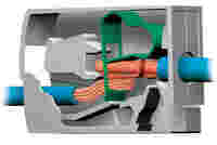
With a new mounting carrier, WAGO has managed to take the advantages users value so much in the WAGO 221 Series and reproduce them in the distribution cabinet itself. The carrier is suited for every 221 Series model. It guarantees easy servicing, inspection, maintenance and accessibility, as well as simple identification and testing of the connected conductors according to VDE 0100-510. The carrier can be snapped onto standard DIN-rails horizontally or vertically, as well as screw-mounted to smooth surfaces. Open on one side, the carrier offers electricians the option of using an operating lever to open the module – even when it is already installed. Conductors can thus be conveniently connected and removed before or after the connector is inserted into the carrier. The design also ensures that a test slot is always accessible.

Proven Quality for New Distribution Cabinets
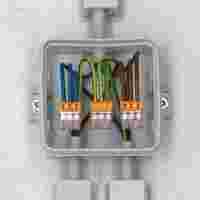
While the combination of 
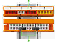
221 Series Splicing Connectors and Mounting Carrier allow standards-compliant expansion of existing wiring installations, there is an even better solution for new building projects: WAGO’s TOPJOB® S Rail-Mount Terminal Blocks. In this type of installation, the rail-mount terminal blocks are snapped directly onto the DIN-rail, which speeds up electrical system wiring. WAGO’s proven push-in connection technology saves time and ensures safety, because the terminal blocks establish a continuously dependable electrical connection.
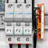
With an eye toward the future, building installations with rail-mount terminal blocks provide greater options for subsequent changes to or expansions of electrical systems, while reducing complications. As a practical benefit, electricians can quickly disconnect conductors, and enjoy the safety of a clear wiring configuration with significantly more flexibility in circuit configuration as compared to installations using PE/N rails.
In addition to transparency and flexibility, safety for the electrical installations in buildings is a sensitive issue. One safety measure is so-called insulation resistance measurement. Since every insulating fault entails a potential hazard, this test is mandatory in fire-prone locations and for public buildings where crowds potentially gather. In practice, installation terminal blocks are used almost exclusively due to the requirements set forth in the standards that a simple measurement of the insulation resistance must be possible for conductors with cross-sections of less than 10 mm2/8 AWG
Voluntary Testing for Greater Safety
Insulation resistance measurement is also an integral part of voluntary testing. With E-CHECK, for example, lessors of private or commercial real estate can repeatedly document the proper condition of the electrical systems before the space is transferred. Some insurers have similarly recognized the advantages of the test and offer their customers reduced premiums if they regularly conduct it.
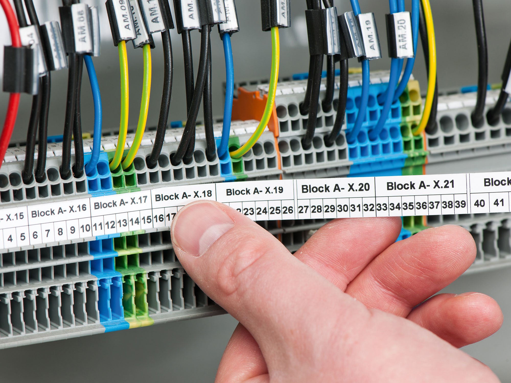
Clear Lines in Electrical Installations
Use of WAGO’s installation rail-mount terminal blocks also helps project a professional image. The appearance of the control cabinet serves as the visible calling card of an electrical installation company, so a tidy, well-structured electrical cabinet provides significant competitive advantages. Labeling each clamping unit with clearly legible marking also contributes to the professional impression made a distribution cabinet makes. With the TOPJOB® S Series, WAGO offers solutions for quickly and clearly marking the rail-mount terminal blocks – up to three easily legible lines of text.
Conclusion
Installations using rail-mount terminal blocks are increasingly replacing conventional connection technology based on PE- and N-rails in both building renovations and new construction. WAGO’s system allows flexible adaptation and saves time during retrofits or expansions. In existing systems, WAGO’s new 221 Series COMPACT Splicing Connectors save both space and time. A carrier allows the connectors to be mounted securely on the DIN-rail.

Inspiration for You

More Helpful Tips

Rail-Mount Terminal Blocks

We have summarized all of the helpful information for properly using WAGO’s rail-mount terminal blocks.

Bühnenbild_Reihenklemmen_2000x1500px.jpg

Safety and Standards

We have summarized all of the important information for safe, standards-compliant usage of WAGO products.

Recommended Reading

More Building Technology Applications

Perfect Electrical Interconnection Technology

Practical tips for installers: Fast, reliable, maintenance-free solutions simplify your everyday tasks.

building_zielgruppen_techniker_sicherheitskleidung_schaltschrank_istock_91679163_2000x2000.jpg
Building Installations